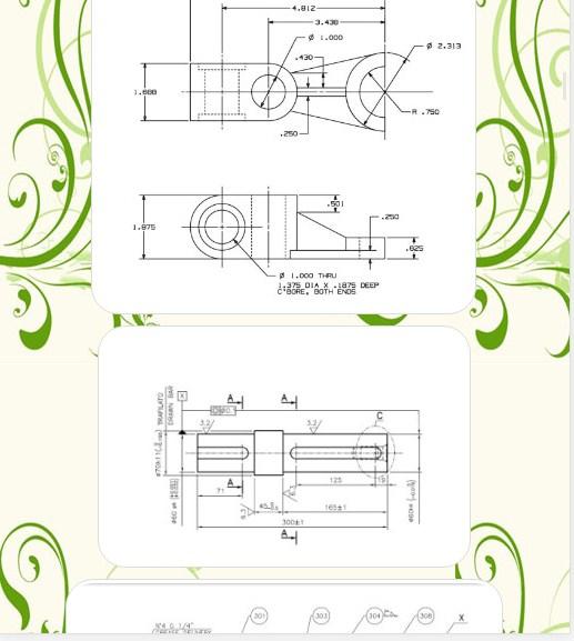
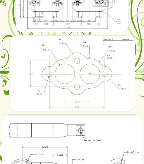
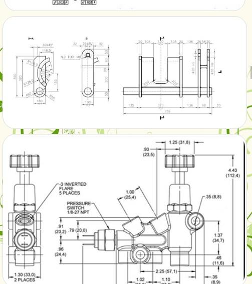
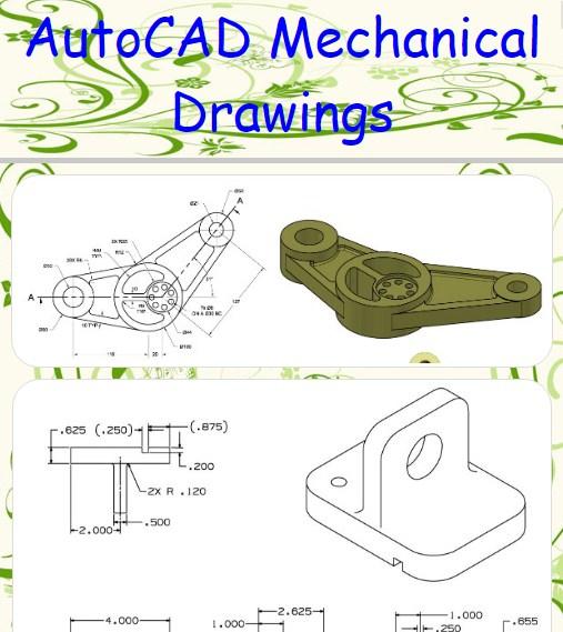
AutoCAD Mechanical Drawings
6.5 24
v1.0 by Taranta
6.5 24
v1.0 by Taranta


Package Name:
Category:
Update Date:
2017-07-04
Latest Version:
1.0
Need Update:
Requirements:
Android 2.3.2+
Report:
Zedge™ Wallpapers & Ringtones
Discover millions of background wallpapers & ringtones or make your own with AI.
9.4 1M+
CM Launcher 3D - Themes, Wallpapers
🏆3D Launcher with Themes & Wallpapers 👍Hide, lock & manage apps easily
8.8 611K+
GO Launcher -Themes&Wallpapers
GO Launcher - Customize your stylish phone with free themes & HD wallpapers!
8.4 750K+